


Guiyang.bai@honno-auto. com
86-13840589744

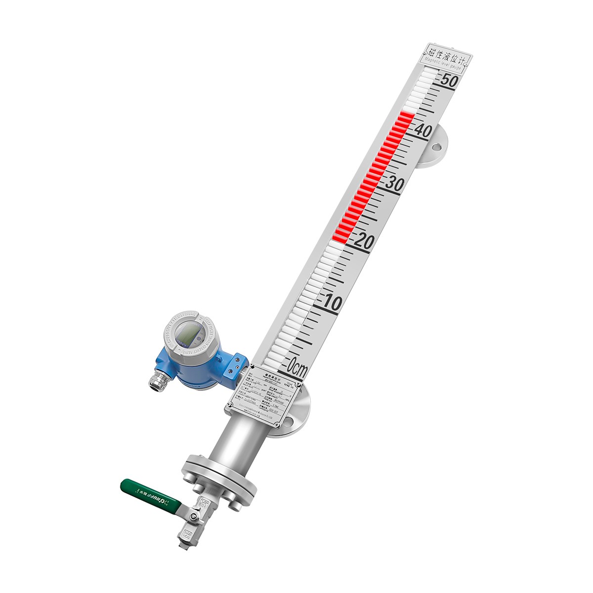
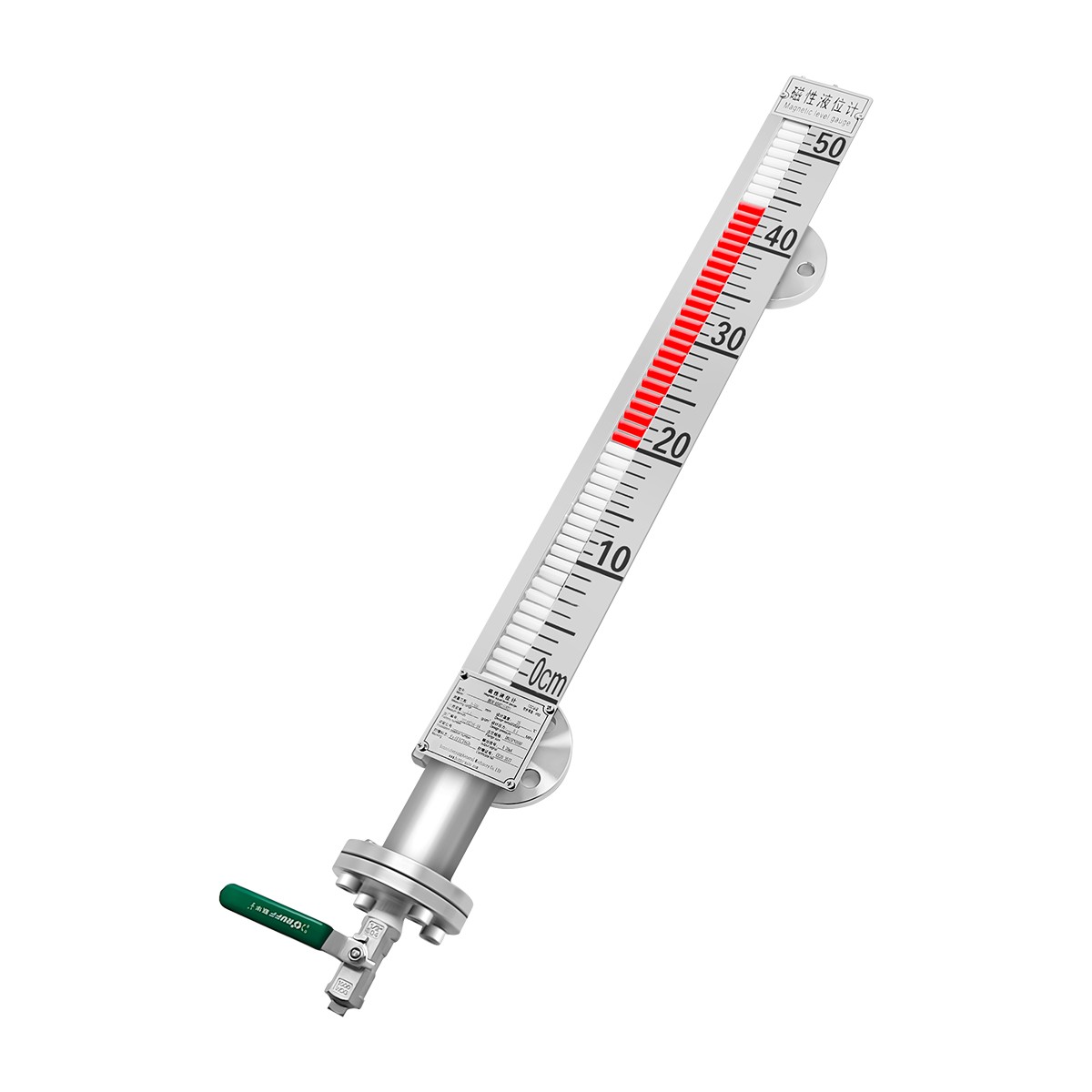
Magnetic flap level gauge with bypass column and flip indicator needing no power. 150–7000 mm, 304/316/UPVC/PTFE-lined, to 100 bar, –160 to 450 ℃, alarm switch and 4–20 mA/HART/magnetostrictive remote option.
The HNL90-A magnetic flap level gauge mounts on a bypass (extension) pipe outside the tank; the tank level is clearly indicated by the flip-column indicator. A magnetic switch can be fitted outside the bypass for electrical contact output, or a level transmitter can be added for remote signal transmission and level control. A magnetic float with a magnet sits inside the bypass; because each flip chip carries a magnet with opposite polarity to the float, the rising float attracts the chips to flip from white to red, showing the actual liquid level height.
The gauge suits wastewater and water treatment, shipbuilding and marine tanks, generator and power equipment, petrochemical storage, food and beverage tanks, electronics manufacturing, dyeing and finishing, chemical and pharmaceutical tanks, rubber and plastics processing, hydraulic machinery reservoirs, large and medium tank level monitoring, and tanks, troughs, pits and corrosive liquid storage.
Good fit: wastewater and water treatment, shipbuilding and marine tanks, generator and power equipment, petrochemical storage, food and beverage tanks, electronics, dyeing and finishing, chemical and pharma tanks, rubber and plastics, hydraulic reservoirs, large/medium tank level monitoring, tanks, troughs, pits and corrosive liquid storage.
Choose HNL90-A when:
You need a local mechanical level indication that requires no external power for the flip column, on a side-mounted bypass column.
The medium is corrosive, flammable, toxic, high-temperature, agitated or contaminated, and a 304, 316, PTFE-lined or UPVC construction suits it.
You also want alarm switches, a 4–20 mA transmitter, HART or a magnetostrictive high-precision remote output.
Confirm with us first when: density is below 0.5 g/cm³, viscosity exceeds 0.05 Pa·S, the required pressure exceeds the selected PN rating, or the medium temperature is outside the chosen temperature version.
The bypass pipe and flip-column display are completely isolated; the simple, sturdy and compact design measures and indicates corrosive, flammable, toxic, high-temperature, agitated or contaminated liquids. The flip display needs no external power supply.
Standard 304 body, standard 316 body, PTFE-lined anti-corrosion, UPVC anti-corrosion, or insulation jacket type. Highly corrosion-resistant materials suit industrial fields across the range; design temperature range –160…450 ℃ per brochure, working temperature by version.
Optional upper/lower limit alarm switches; remote output in 4–20 mA standard, 4–20 mA with HART, or 4–20 mA magnetostrictive high-precision type. Short-circuit protection is provided on the signal output.
| Model | HNL90-A — Magnetic flap (magnetic float) level gauge |
|---|---|
| Measuring range | 150…7000 mm |
| Repeatability | <±10 mm (magnetostrictive <±1 mm optional) |
| Non-linearity BFSL | Max 0.5 % FS (magnetostrictive ≤±0.05 % FS optional) |
| Response time | <150 ms (magnetostrictive <5 ms optional) |
| Resolution | 10 mm (magnetostrictive <±10 μm optional) |
| Temperature influence | ≤±0.45 % / 55 ℃; zero point settable through menu |
| Allowable pressure | Max 100 bar |
| Medium density / viscosity | Density ≥0.5 g/cm³; viscosity ≤0.05 Pa·S |
| Signal output | 4–20 mA, switch output, HART protocol (short-circuit protection) |
| Supply voltage | 24±3 VDC (polarity protection); overpressure protection max 36 VDC |
| Power / load | Power consumption max 22.5 mA; load RL = 500 Ω; switching load current 5 A |
| Explosion-proof grade | Exd IIC T5 |
| Working temperature | –40…300 ℃ |
| Transport / storage | –20…85 ℃ |
| Vibration / shock | Sine 20 g, 25 Hz–2 kHz; piston 4.4 g, 25–200; impact 50 g/6 ms; free fall 1 m |
| Protection level | IP65 (IP68 optional), with matching connectors |
| Mechanical connection | DN25 flange standard; others customized to requirement; terminal wiring |
| Wetted parts / shell | 304 / 316 / UPVC; aluminum shell |
Ordinary analog two-wire output: terminal 24+ to power supply, terminal A+ to signal line. Alarm switch output provides always-open (NO) and always-closed (NC) contacts. Magnetostrictive analog two-wire output connects to 24 VDC supply with ammeter and load RL ≥250 Ω. Configure NO/NC and alarm limits to match the pump or interlock logic.
| Item | Specification |
|---|---|
| Bypass pipe | 60.3×2 (PN6–PN40); 60.3×2.6 (PN64); 65×3.5 (PN100) |
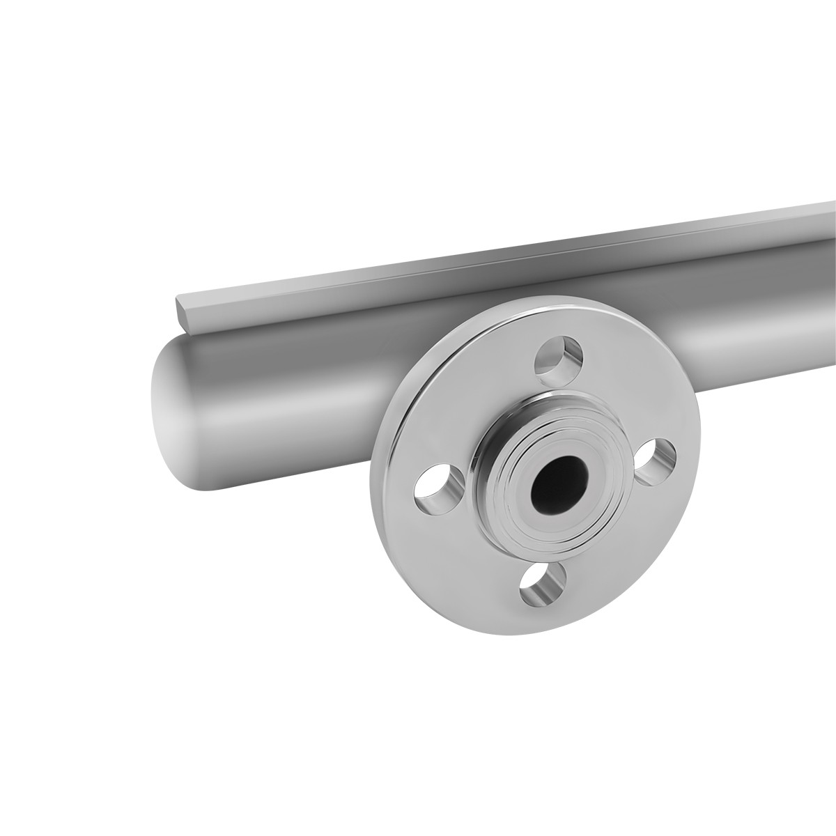
| Side-mounted flange | DN15–DN100; DN25 standard if not specified |
| Drain / vent | Bottom drain valve G1/2" pipe thread; top vent plug G1/2" pipe thread |
| UPVC limit | Anti-corrosion media; max pressure 6 bar |
| Code segment | Code | Description |
|---|---|---|
| Basic type | 00 | Standard type 1, body 304 |
| 01 | Standard type 2, body 316 | |
| 02 | Anti-corrosion, PTFE lined | |
| 03 | Anti-corrosion, body UPVC | |
| 04 | Insulation jacket type | |
| Measurement type | A | Level |
| B | Interface | |
| Measuring range | 150…7000 / X | 0–150 to 0–7000 mm; X special custom range |
| Alarm method | A | No alarm |
| B | Upper limit alarm | |
| C | Lower limit alarm | |
| D | Upper and lower limit alarms | |
| Remote signal output | 1 | No remote transmission |
| 2 | 4–20 mA standard | |
| 3 | 4–20 mA with HART | |
| 4 | 4–20 mA magnetostrictive high-precision | |
| Process connection | A01–A09 / X | DN15, DN20, DN25, DN40, DN50, DN65, DN80, DN100, 1" flange; X special |
| Pressure rating | 1 | PN10 |
| 2 | PN16 | |
| 3 | PN25 | |
| 4 | PN40 | |
| 5 | PN64 | |
| Medium temperature | A01 | –40…80 ℃ |
| A02 | –40…120 ℃ | |
| A03 | –40…200 ℃ | |
| A04 | –40…250 ℃ | |
| Drain valve | 1 | No drain valve |
| 2 | Equipped with drain valve | |
| Explosion-proof | 1 | Non-explosion-proof |
| 2 | Explosion-proof type |
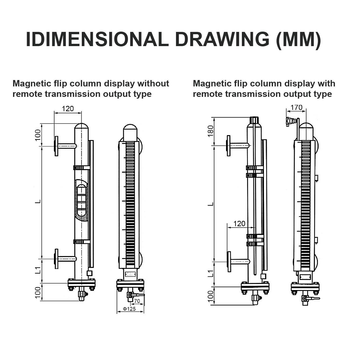
Side-mounted bypass column with upper and lower tank flanges, internal bypass float and external magnetic flip column; versions with or without remote transmission. Overall length L matches the ordered range; L1 is set from customer parameters (density, pressure, temperature), max 301 mm.
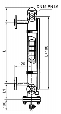
Mount the bypass column vertically alongside the tank, with the upper and lower flanges aligned to the tank connections so the liquid level in the bypass matches the tank. Keep the column clear of inlet turbulence, agitator action and wall buildup. For interface service, confirm the two densities and the interface range. Protect the column from mechanical impact; keep the drain and vent connections accessible for maintenance.
Water and wastewater: treatment plants, reservoirs, troughs and pits.
Process industry: petrochemical, chemical and pharma tanks, food and beverage, dyeing and finishing.
Marine and power: shipbuilding tanks, generator and power equipment, hydraulic reservoirs.
Special media: corrosive, toxic, high-temperature or agitated liquids where local indication plus alarm/remote output is required.
Send: medium and density, interface requirement (if any), temperature and pressure, tank size and connection size, required range, alarm and remote-output preference, material requirement (304/316/PTFE/UPVC), and any hazardous-area classification. We will confirm the version and selection code before quoting.
Is local indication available without power?
Yes. The magnetic flip column is a mechanical local indicator that needs no external power; red/white chips follow the float. Power is only required when an alarm switch, 4–20 mA transmitter, HART or magnetostrictive remote output is fitted.
How should bypass connections be positioned to avoid an unreadable dead zone?
Align the upper and lower bypass flanges with the tank connections and keep the column vertical; avoid mounting where inlet jets or agitation affect the bypass. Confirm the lower connection sits below the minimum level and the upper above the maximum level for the required range.
Can lined construction handle corrosive or toxic process liquids?
PTFE-lined and UPVC versions are offered for anti-corrosion duty; 304/316 versions suit general service. Confirm the medium against the wetted material; UPVC is limited to 6 bar and anti-corrosion media.
Do magnetic switches provide independent pump and overflow interlocks?
Optional upper and lower alarm switches give NO/NC contacts for pump control, dry-run or overflow interlock. Set the alarm limits and fail-safe logic; switching load current is 5 A max.
What maintenance prevents the bypass float from sticking in dirty liquids?
In dirty or viscous service, inspect the bypass and float periodically through the drain/vent connections; flush or clean when buildup appears. Keep the density and viscosity within rated limits (≥0.5 g/cm³, ≤0.05 Pa·S) so the float moves freely.
HNL90-A Magnetic Flap Level Gauge Datasheet (PDF) — view all product manuals on our Download page »
Send us the medium, density, temperature, pressure and range. We will confirm the material, version and selection code before we quote.
Send us your application details »
Contact: HongNuo
Phone: 13840589744
Tel: 86-13840589744
Email: Guiyang.bai@honno-auto. com
Add: Zhongguancun Innovation Center, No. 28 Huahai Road, Shenyang Economic and Technological Development Zone, Liaoning Province
We chat
