Guiyang.bai@honno-auto. com
86-13840589744
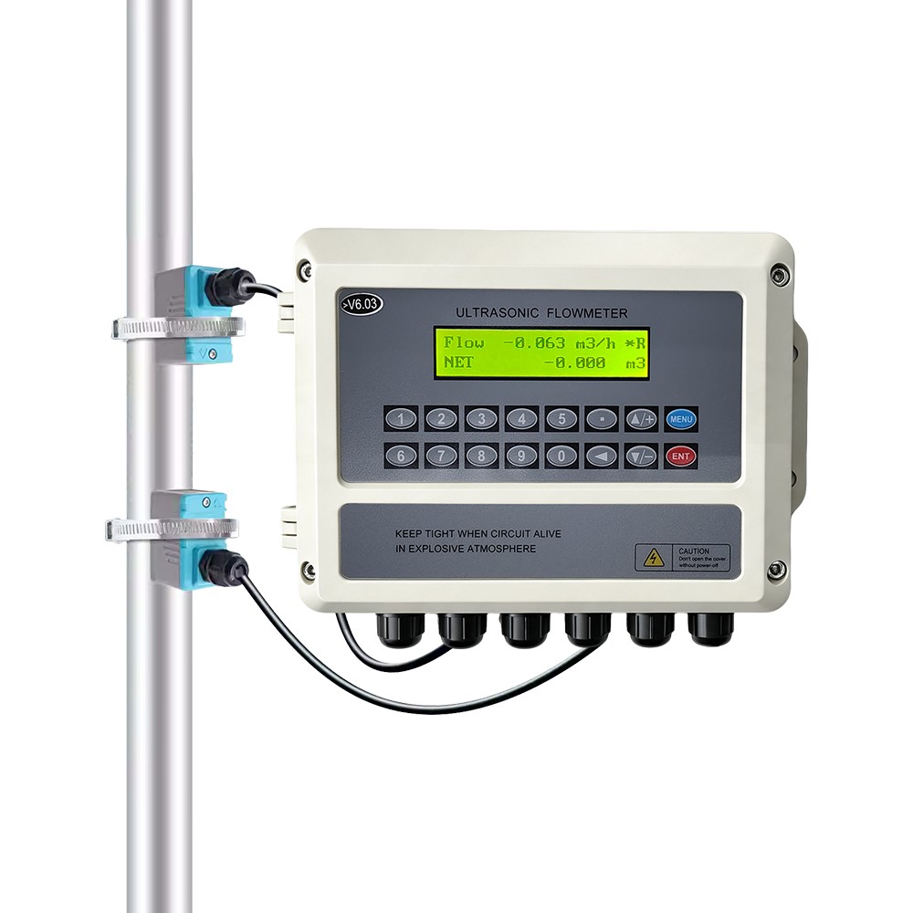
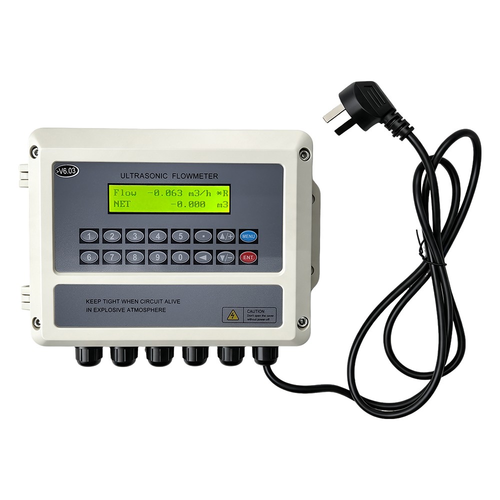
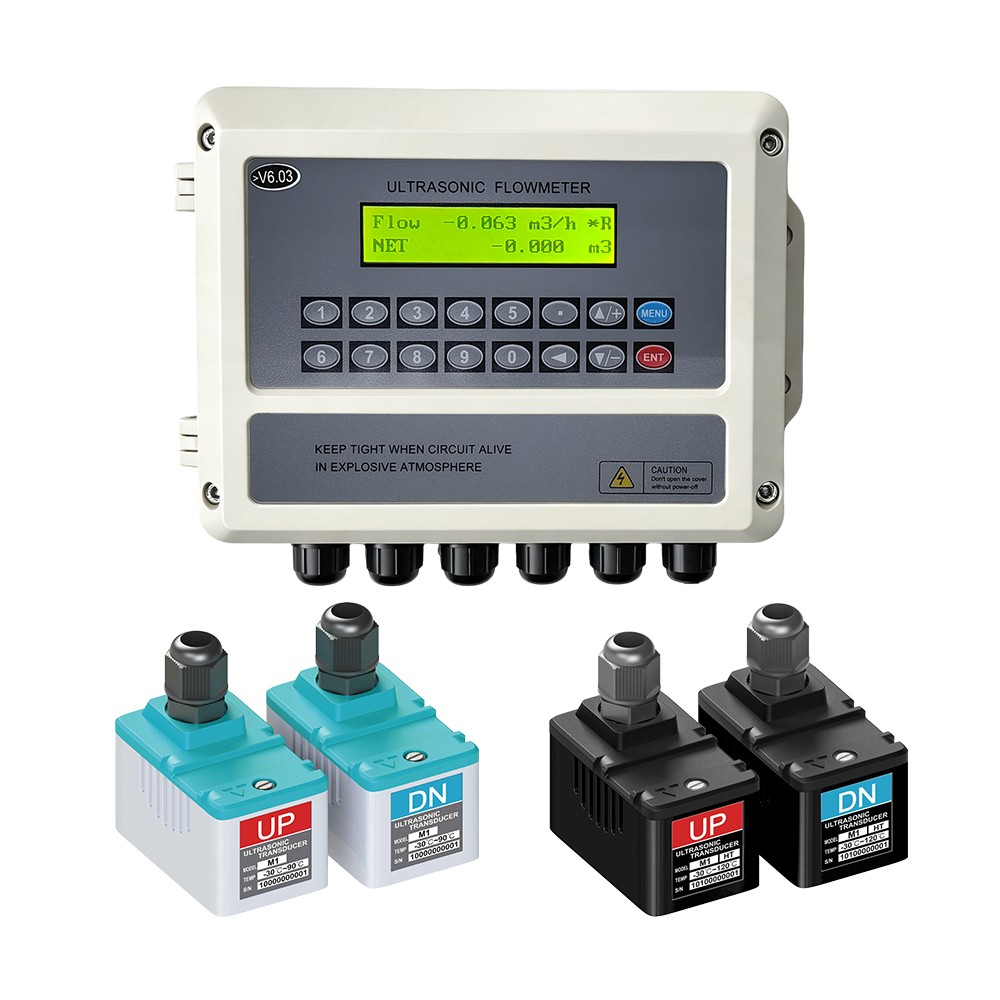
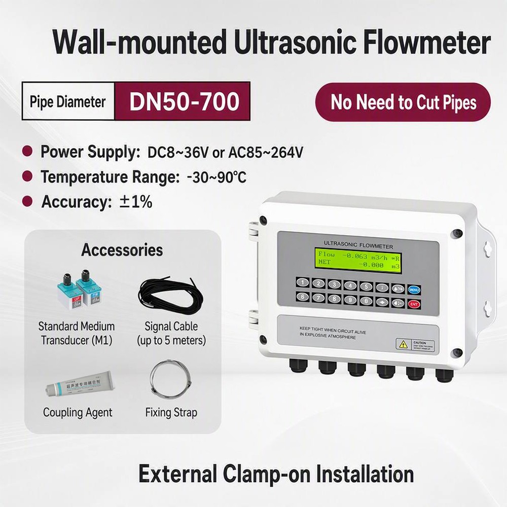
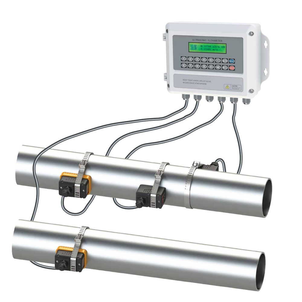
HNF100-A basic transit-time split ultrasonic flow meter and heat meter. The converter mounts on a wall or 35 mm DIN rail and connects by dedicated cable up to 200 m to clamp-on or insertion transducers. Pipe OD, wall thickness, material, lining and fluid are keyed in to compute spacing and V/Z method; a 2×20 backlit LCD shows instantaneous flow, net/positive/negative totals, heat rate and total heat.
The HNF100-A is the basic series of transit-time ultrasonic flow meter and heat meter in a split design. The converter is fixed on the wall or on a 35 mm DIN rail and connected by dedicated ultrasonic cable to clamp-on or insertion transducers on the pipe, so it suits locations where the electronics must stay accessible and readable. Pipe outside diameter, wall thickness, material, lining and fluid type are keyed in through the keypad; the converter computes transducer spacing and the V or Z mounting method. Instantaneous flow, net/positive/negative totalisers, heat rate and total heat are shown on a 2×20 backlit dot-matrix LCD and are available on current, pulse, relay, frequency and RS485 outputs. Add two PT100 sensors on the supply and return legs and the same unit meters heating and cooling energy.
Clamp-on transducers fix to the outside wall with steel band or wire rope; the pipe stays intact and the process keeps running. Where access is limited or the pipe cannot be clamped, insertion probes enter through a ball-valve boss. One converter covers DN15–DN6000, with standard transducers to 90 ℃ and high-temperature or insertion versions to 160 ℃. The same electronics handle flow and heat, with heat totalised in GJ, kcal, kWh or BTU.
Good fit: district heating and cooling, HVAC and building energy, boiler and heat-exchanger systems, supply/return heat, chilled and condenser water, water supply and drainage, process water, chemical and petrochemical, metallurgy, power, water treatment and sewage, pump and pipeline monitoring, BTU billing, retrofit of existing pipes.
Choose HNF100-A when:
You need a non-invasive clamp-on measurement on an existing pipe, with no cutting and no shutdown.
The converter must be wall- or DIN-rail mounted away from the transducer, with cable runs up to 200 m.
Flow and heat metering, two alarm relays, batch control, data logging and RS485 Modbus integration are required.
Confirm with us first for gases, liquids that do not conduct ultrasound, dirty or highly viscous fluids, pressure above the selected transducer rating, or pipes outside the listed materials and sizes.
Two transducers transmit and receive ultrasound alternately. At zero flow the upstream and downstream transit times are identical; when the liquid moves, the downstream time shortens and the upstream time lengthens. The difference is proportional to flow velocity, and the converter integrates it over the pipe section. Pipe OD, wall thickness, material, lining and fluid are entered in the menu; the converter calculates spacing, number of passes and V/Z method. Live signal strength, Q value and transit-time ratio are shown for installation acceptance.
| Model | HNF100-A — basic split-type ultrasonic flow meter / heat meter |
|---|---|
| Principle | Transit-time ultrasonic; single or dual channel |
| Flow direction | Forward, reverse and net |
| Pipe size | Clamp-on DN15–DN6000; insertion DN50–DN6000 |
| Pipe material | Steel, stainless, cast iron, ductile iron, copper, PVC, PE, ABS, FRP, glass, cement; lining supported |
| Liquid | Water, seawater, sewage, acid and alkali, alcohol, oils and other sound-conducting liquids |
| Fluid temperature | −30…90 ℃ standard; −30…160 ℃ high-temperature and insertion |
| Display | 2×20 dot-matrix LCD, adjustable backlight and contrast |
| Keypad | 16-key (wall) or 4-key (DIN rail) membrane keypad |
| Current output | 4–20 / 0–20 / 0–24 mA; accuracy better than 0.1 %; load 600 Ω max. |
| Pulse / OCT output | OCT, electrically isolated, DC 60 V / 100 mA; pulse width 6–1000 ms |
| Relay output | 2 relays, AC 125 V / DC 28 V, 1 A; two flow alarms with buzzer |
| Frequency output | 0–999 Hz, proportional to flow |
| Analog input | AI3 / AI4 / AI5, 4–20 mA, plus pressure input |
| Temperature input | 2× PT100, three-wire (T1 supply, T2 return) |
| Communication | Isolated RS485: MODBUS RTU/ASCII, M-BUS, FUJI extension |
| Heat metering | Enthalpy (GB-CJ128) or ΔT method; units GJ, kcal, kWh, BTU; supply/return side selectable |
| Power supply | Wall: AC 110–220 V or DC 8–36 V; DIN rail: DC 24 V |
| Transducer cable | Dedicated ultrasonic cable, up to 200 m |
| Mounting | Wall: 4× Φ6 expansion bolts; DIN rail: 35 mm clip |
| Converter size | Wall 210×226×58 mm; DIN rail 91×91×35 mm |
| Type | Model | Pipe size | Fluid temperature | Mounting |
|---|---|---|---|---|
| Clamp-on standard | S1 | DN15–DN100 | −30…90 ℃ | Steel band or wire rope; couplant supplied; no pipe cutting |
| M1 | DN50–DN700 | −30…90 ℃ | ||
| L1 | DN300–DN6000 | −30…90 ℃ | ||
| Clamp-on high-temperature | S1-HT | DN15–DN100 | −30…160 ℃ | Black high-temperature body for boiler, heat-exchanger and process lines |
| M1-HT | DN50–DN700 | −30…160 ℃ | ||
| L1-HT | DN300–DN6000 | −30…160 ℃ | ||
| Insertion | ATC-1 | DN50–DN6000 | −30…160 ℃ | Standard, ball valve |
| ATC-2 | DN50–DN6000 | −30…160 ℃ | Extended stem | |
| ATP-1 | DN200–DN6000 | −30…160 ℃ | Parallel insertion |
Insertion transducers are rated to 1.6 MPa working pressure; higher pressure or pipe-section sensors are available on request. Pressure-tight installation (PCT-1 type) allows fitting without shutting down the line.
| Model | Type | Pipe size | Temperature | Installation |
|---|---|---|---|---|
| CT-1 | Clamp-on | ≥DN50 | −40…160 ℃ | No shutdown |
| TCT-1 | Insertion | ≥DN50 | −40…160 ℃ | Line shut down |
| PCT-1 | Pressure insertion | ≥DN50 | −40…160 ℃ | No shutdown |
| SCT-1 | Small-bore insertion | ≤DN40 | −40…160 ℃ | Line shut down |
| Item | Options | Notes |
|---|---|---|
| Converter | Wall mounted | 35 mm DIN rail | Same firmware and I/O on both housings |
| Supply | AC 110–220 V | DC 8–36 V (wall) | DC 24 V (rail) | State the site supply when ordering |
| Flow transducer | S1 / M1 / L1 clamp-on | ATC-1 / ATC-2 / ATP-1 insertion | Choose by pipe OD and access |
| Temperature class | Standard −30…90 ℃ | High temperature −30…160 ℃ | Insertion types rated to 160 ℃ |
| Heat metering | Not fitted | PT100 pair (CT-1 / TCT-1 / PCT-1 / SCT-1) | Heat meter = converter + transducers + PT100 pair |
| Outputs | 4–20 / 0–20 / 0–24 mA, OCT, 2 relays, 0–999 Hz | Configured in the menu, no hardware change |
| Cable | Standard length on request, up to 200 m | Dedicated ultrasonic cable only |
Full pipe at the measuring point; clean, smooth surface free of scale, rust and paint.
Straight run: 10D upstream and 5D downstream; 30D from a pump outlet or a half-open valve.
Avoid vibration and strong electrical interference; keep away from VFDs, transmitters and HV cables.
Ground the converter housing, transducers and cable shield; do not share the supply with a VFD.
Use the dedicated ultrasonic cable in tray or conduit, clear of power cables.
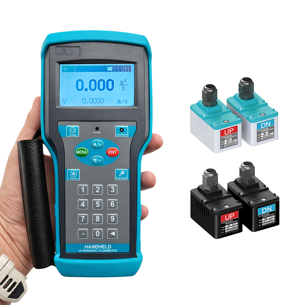
Clamp-on: V method DN15–200, Z method DN200–6000; insertion: V DN50–300, Z DN50–6000, parallel from DN200. Transducers are marked UP (red, upstream) and DN (blue, downstream); a pair must carry the same serial code.
Net / positive / negative accumulators plus daily, monthly and yearly records; power-off flow make-up keeps totals continuous; power-on/off events logged with the flow at each event.
Two alarm channels with independent upper and lower limits; a relay can drive an external alarm or beacon.
Built-in batch controller switches OCT or relay on a preset volume, started by key or analog input edge.
11-point linearity correction, meter factor, damping, low-flow cut-off and menu password lock.
Energy and HVAC: district heating and cooling, chilled and condenser water, boiler and heat-exchanger systems, supply/return heat, BTU billing.
Water and industry: water supply and drainage, process water, treatment and sewage, chemical and petrochemical, metallurgy, power.
Monitoring and retrofit: pump and pipeline monitoring, energy audit, retrofit of existing pipes without cutting the line.
Send: pipe outside diameter and wall thickness, pipe material and lining, fluid type and temperature range, normal and maximum flow, required transducer style (clamp-on or insertion), heat metering PT100 pair, outputs, supply and cable length. We will confirm the transducer model and configuration before quoting.
Can clamp-on transducers avoid cutting the pipe?
Yes. Clamp-on transducers fix to the outside wall with steel band or wire rope; the pipe stays intact and the process keeps running. Insertion probes enter through a ball-valve boss where the pipe cannot be clamped.
Which sensors cover DN15 to DN6000?
Clamp-on S1 covers DN15–100, M1 DN50–700 and L1 DN300–6000; insertion ATC-1/ATC-2 cover DN50–6000 and ATP-1 parallel insertion DN200–6000. High-temperature -HT versions reach 160 ℃.
Does the logger retain daily and monthly totals?
Yes. Net, positive and negative accumulators keep daily, monthly and yearly records; power-off make-up keeps totals continuous, and power-on/off events are logged with the flow.
How are PT100 sensors connected to calculate supply and return energy?
Two three-wire PT100 inputs take T1 supply and T2 return. Heat is computed by enthalpy (GB-CJ128) or ΔT method, totalised in GJ, kcal, kWh or BTU, supply/return side selectable.
What outputs support batch control integration?
Configurable 4–20/0–20/0–24 mA, isolated OCT pulse, two relays, 0–999 Hz and isolated RS485 Modbus RTU/ASCII, M-BUS, FUJI. The batch controller switches OCT or relay on a preset volume.
Send the pipe size, material, fluid, temperature and required output. We will confirm the transducer model and configuration before quotation.
Send us your application details »
Contact: HongNuo
Phone: 13840589744
Tel: 86-13840589744
Email: Guiyang.bai@honno-auto. com
Add: Zhongguancun Innovation Center, No. 28 Huahai Road, Shenyang Economic and Technological Development Zone, Liaoning Province
We chat