Guiyang.bai@honno-auto. com
86-13840589744
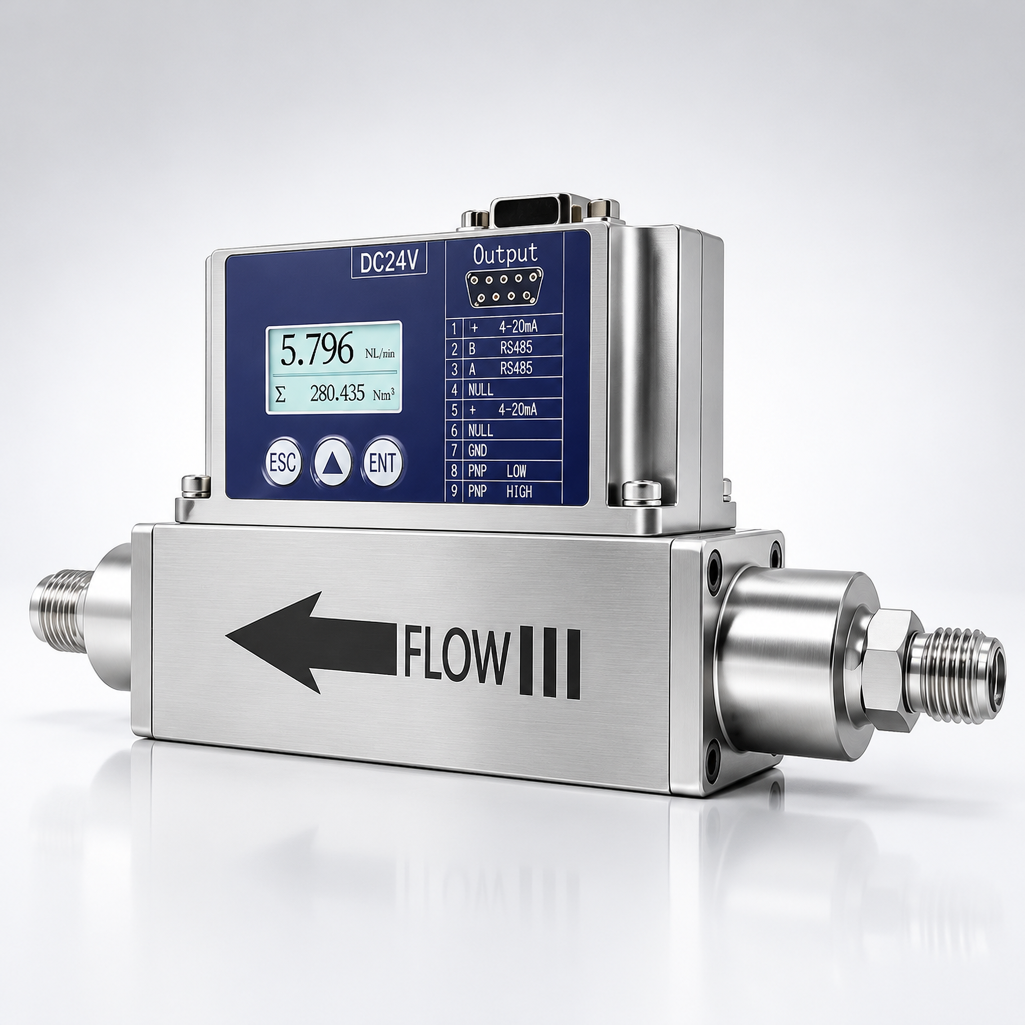
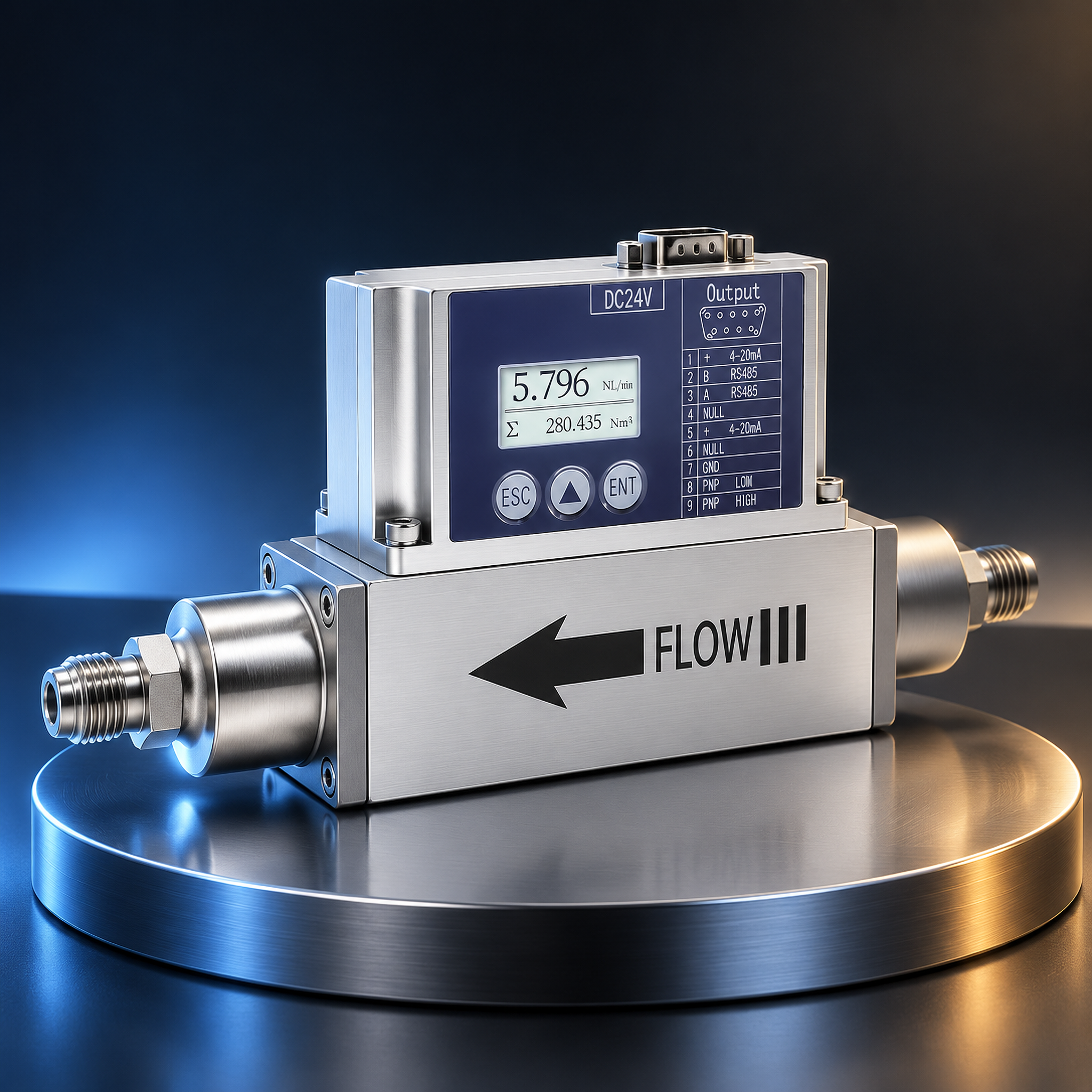
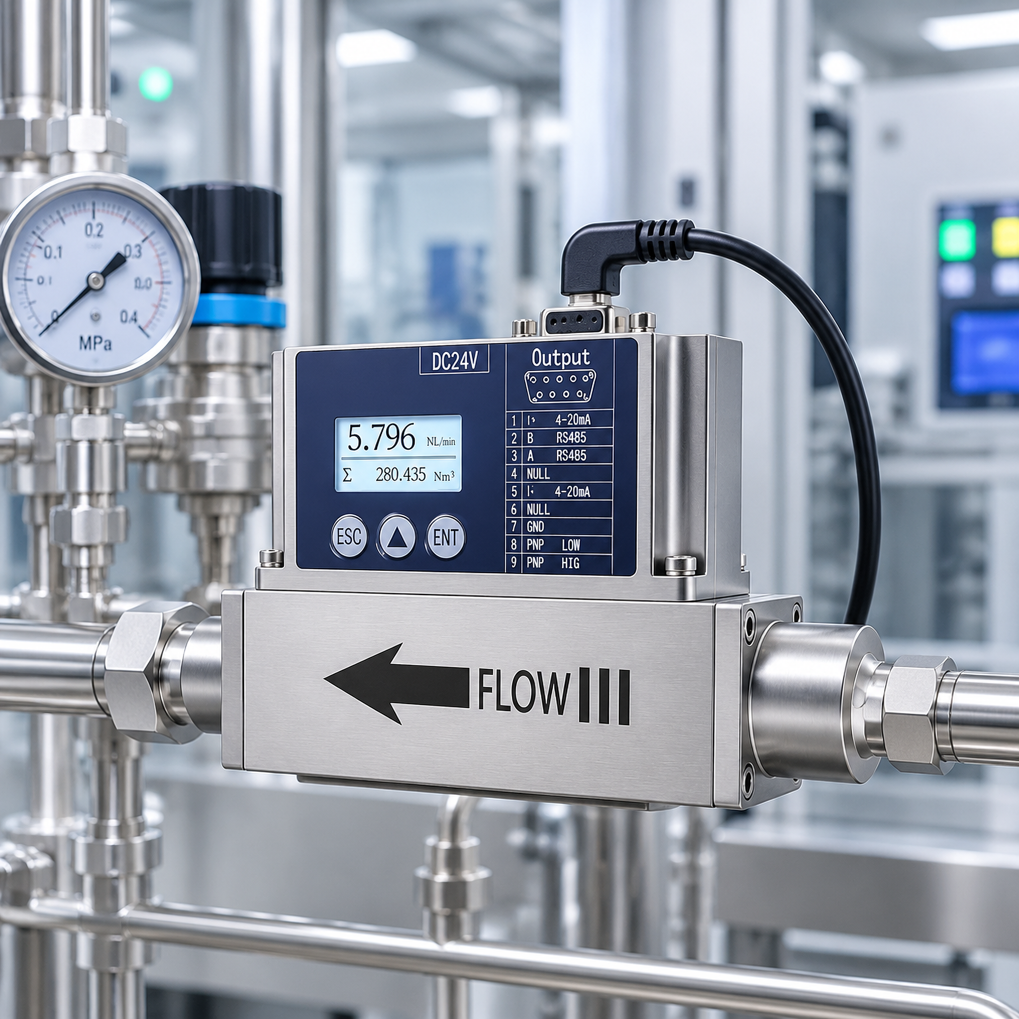
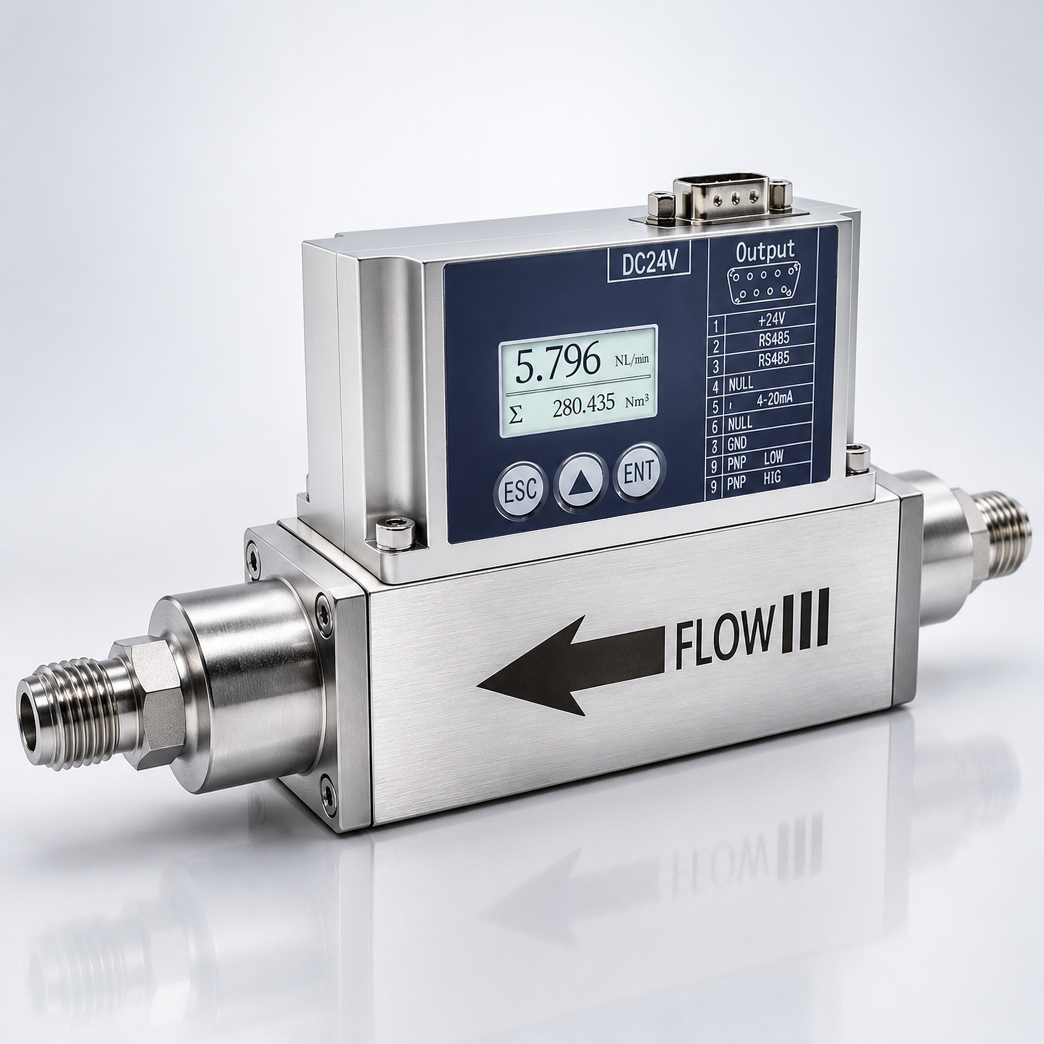
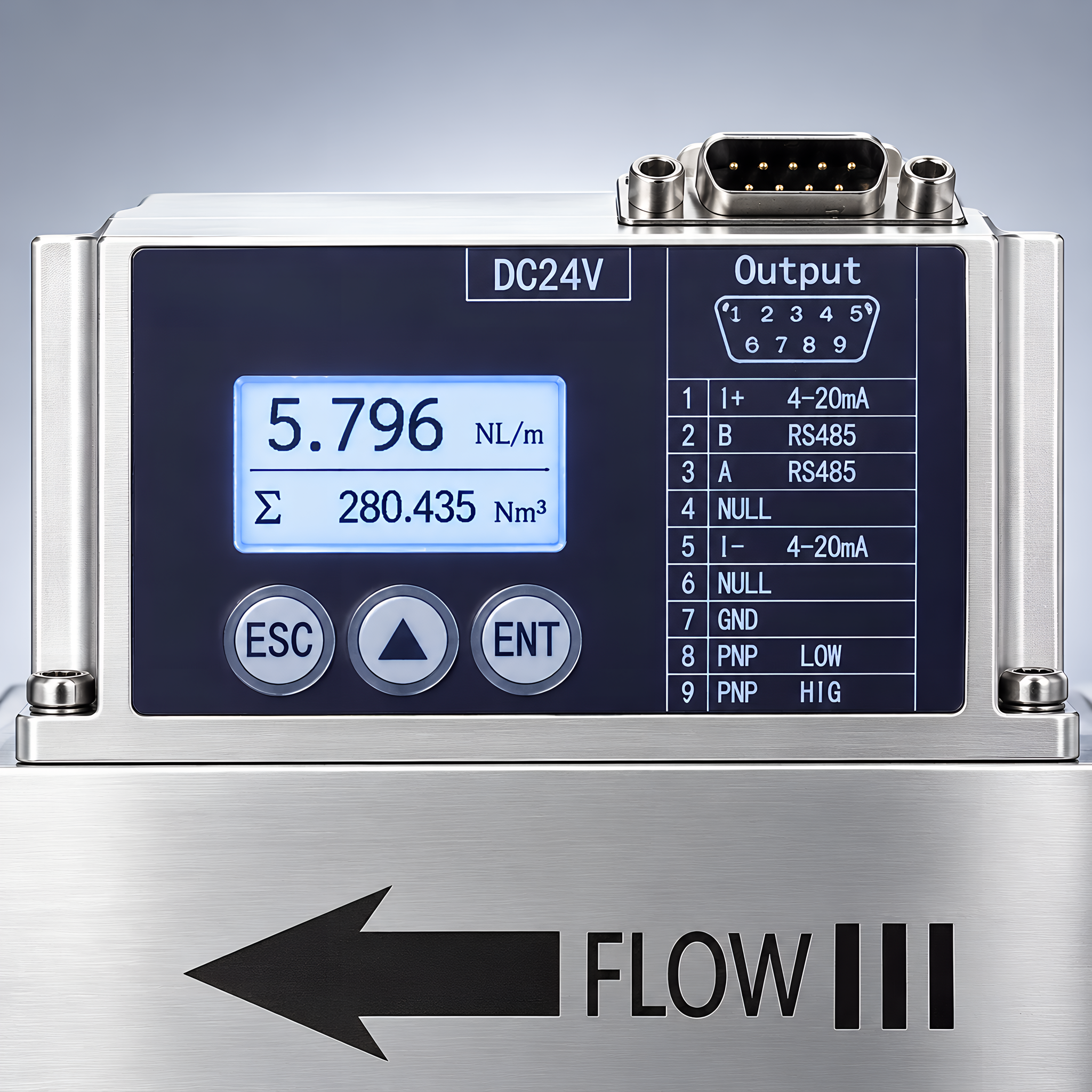
Micro gas mass flow meter for small-flow measurement and process control, built around an advanced MEMS flow-sensing chip for clean gases. Low-cost, easy installation on different pipe diameters, no temperature or pressure compensation, replacing traditional displacement or differential-pressure meters. Stable zero, high accuracy and repeatability, standard mechanical interface; LCD shows instantaneous and cumulative flow, with 4–20 mA or 1–5 V analogue, optional pulse/PNP, and RS485 Modbus RTU. 0.2 SCCM to 1000 NL/h, 1:100 range ratio; selectable air, N₂, O₂, CH₄, Ar, CO₂, He, H₂, C₃H₈, other gases on request.
The HNF80-G micro gas mass flow meter is designed for small-flow gas measurement and process control, built around an advanced MEMS (micro-electro-mechanical system) flow-sensing chip. It suits a wide range of clean gases; its packaging technology allows installation on different pipe diameters at low cost and with easy mounting. No temperature or pressure compensation is required, and it can replace traditional displacement-type or differential-pressure flow meters. The zero point is stable, accuracy and repeatability are high across the range, and the standard mechanical interface simplifies integration. A clear LCD shows instantaneous and cumulative flow; the unit offers 4–20 mA or 1–5 V analogue output, optional pulse and PNP output, plus RS485 communication on the standard Modbus RTU protocol.
The meter covers a minimum measurable flow of 0.2 SCCM and a maximum of 1000 NL/h, with a 1:100 range ratio. Factory-selectable gases include air, N₂, O₂, CH₄, Ar, CO₂, He, H₂ and C₃H₈; other gases can be configured on request. On-board settings cover flow-factor calibration, 4–20 mA lower/upper range, damping, cutoff, flow and totalizer units, and Modbus device ID and baud rate, so the meter adapts to different gases and process conditions.
Good fit: aerospace, semiconductor processing, medical and biological equipment, electronic component manufacturing, automotive, iron and steel metallurgy, marine electronics, industrial gas production, laboratory gas analysis, gas mixing and dilution, clean-gas process control, medical oxygen and breathing-gas monitoring, gas chromatography support, packaging N₂/CO₂ dosing, glove-box and chamber gas management.
Choose HNF80-G when:
You measure clean gas at very small flow, from SCCM up to 1000 NL/h, and need direct mass flow without P/T compensation.
You need a local LCD with instantaneous and cumulative flow, plus analogue, pulse/PNP or RS485 Modbus output to a PLC or data system.
Standard thread connection, low-cost installation and configurable gas/units are priorities.
Confirm with us first when: the gas is humid, oily or contaminated; medium temperature is outside −10…55 ℃; pressure exceeds 1.1 MPa; or the flow falls outside the selected range.
The MEMS flow-sensing chip measures the heat-transfer or flow signal from the gas passing the sensor; because it reads mass flow directly, no temperature or pressure compensation is needed. The transmitter drives the LCD, scales the analogue and pulse/PNP outputs, and communicates over RS485 Modbus RTU. The on-board FlowFactor compensates for cross-section velocity distribution and application-specific conditions; display value = instrument factor × actual measured value.
| Model | HNF80-G — MEMS micro gas mass flow meter |
|---|---|
| Measured variable | Gas mass flow (instantaneous and cumulative) |
| Measurable flow | Minimum 0.2 SCCM; maximum 1000 NL/h; range ratio 1:100 |
| Accuracy | Below 100 NL/min: ±(1.0 + 0.4 FS)%; above 100 NL/min: ±(1.5 + 0.2 FS)% (measured at 25 ℃, 101.32 kPa, dry air) |
| Response time | 50 ms |
| Warm-up time | 3–4 minutes; preheating recommended before precision measurement |
| Medium temperature | −10…55 ℃ |
| Working pressure | ≤1.1 MPa |
| Humidity | <95 % RH (no frost, no ice) |
| Reference temperature | 0 / 20 / 25 ℃ user-adjustable; default 25 ℃ |
| Selectable gases | Air, N₂, O₂, CH₄, Ar, CO₂, He, H₂, C₃H₈; other gases on request |
| Power supply | DC 24 V / 2.5 W (with accompanying power adapter) |
| Display | LCD; instantaneous flow and units on line 1, cumulative flow and units on line 2 |
| Analogue output | 4–20 mA or 1–5 V |
| Other output | Pulse output and PNP output (optional); alarm high/low level optional |
| Communication | RS485, standard Modbus RTU; device ID 0–255; baud 4800 / 9600 / 19200; parity None/Odd/Even; stop bit 1/2 |
| Process connection | PT1/2 or G1/4 female thread; NPT1/2 or G1/4 female; standard bushing, quick-insert or pagoda adapters available |
| Protection class | IP40 |
| Option | Choices |
|---|---|
| Gas type | Air, N₂, O₂, CH₄, Ar, CO₂, He, H₂, C₃H₈; custom gas on request |
| Analogue output | 4–20 mA or 1–5 V |
| Switch / pulse | Pulse output optional; PNP output optional; alarm high or low level optional |
| Thread | PT1/2, G1/4, NPT1/2 female; bushing, quick-insert or pagoda adapter |
| Flow units | mL/min, NL/min, m³/h, SCCM, NL/h; totalizer units m³ or NL |
| Communication | RS485 Modbus RTU; address 0–255; baud 4800/9600/19200; parity and stop bit selectable |
| Wire color | Function |
|---|---|
| Yellow | 4–20 mA current I+ |
| Black | 4–20 mA current I− |
| Red | RS485 communication output A |
| Brown | RS485 communication output B |
| Blue | Power 0 V |
| Green | Power 24 V |
| Orange | PNP output (optional) |
Working supply is DC 24 V / 2.5 W with the accompanying adapter. Do not wire with power on; keep signal wiring separate from power and high-voltage lines.
Mount according to the flow arrow; horizontal or vertical mounting is supported.
Reserve an upstream straight section of 5×DN. Downstream straight section: 20×DN standard; 25×DN with two 90° elbows; 40×DN on a three-direction pipe with two elbows; 55×DN when a control valve is mounted downstream.
Fit a filter upstream if the gas may carry dust or foreign matter.
Allow 3–4 minutes warm-up before precision microflow measurement.
FlowFactor: calibration correction factor compensating velocity distribution and application conditions; display value = instrument factor × measured value.
Range: lower range corresponds to 4 mA, upper range to 20 mA.
Damp Factor: default 0, range 0–20; lower value reacts faster to flow jumps, higher value smooths the display.
Cutoff: percentage, default 0.05, range 0–100; flow below the cutoff percentage of maximum range is suppressed.
Units: flow unit mL/min, NL/min, m³/h, SCCM, NL/h; totalizer unit m³ or NL; cumulative data can be cleared.
Modbus: default 9600, 8 data bits, 1 stop bit, none parity; floating-point order 2143; read function code 03; address set in menu, 0–255.
Electronics & semiconductor: semiconductor processing, electronic component manufacturing, gas chromatography support, clean-gas process control.
Life sciences & medical: medical and biological equipment, medical oxygen and breathing-gas monitoring, laboratory gas analysis.
Industrial gas: industrial gas production, gas mixing and dilution, glove-box and chamber management, packaging N₂/CO₂ dosing.
Other: aerospace, automotive, iron and steel metallurgy, marine electronics.
Send: gas type, normal and maximum flow, operating pressure and temperature, required analogue/pulse/PNP/RS485 output, thread standard and size, and any adapter needed. We will confirm the configuration before quoting.
Which clean gases are factory selectable?
Air, N₂, O₂, CH₄, Ar, CO₂, He, H₂ and C₃H₈ are selectable; other gases can be configured on request. Set the gas type and FlowFactor to match the process medium.
Can it measure as low as 0.2 SCCM?
Yes. The minimum measurable flow is 0.2 SCCM and the maximum is 1000 NL/h, with a 1:100 range ratio; accuracy is stated against dry air at 25 ℃ and 101.32 kPa.
Does RS485 use standard Modbus RTU?
Yes. Communication is RS485 on the standard Modbus RTU protocol; device address 0–255, baud 4800/9600/19200, parity None/Odd/Even and stop bit 1/2 are selectable in the menu.
How are reference temperature and flow factor configured for different gases?
Reference temperature is user-adjustable at 0/20/25 ℃ (default 25 ℃). FlowFactor is the calibration correction factor for velocity distribution and application conditions; the display value equals instrument factor × actual measured value.
What warm-up time is recommended before precision microflow measurement?
Allow 3–4 minutes warm-up after power-on; preheating is recommended before taking precision microflow readings.
HNF80-G MEMS Gas Mass Flow Meter Datasheet (PDF) — view all product manuals on our Download page »
Send the gas, flow, pressure, temperature and required output. We will confirm the configuration before quotation.
Send us your application details »
Contact: HongNuo
Phone: 13840589744
Tel: 86-13840589744
Email: Guiyang.bai@honno-auto. com
Add: Zhongguancun Innovation Center, No. 28 Huahai Road, Shenyang Economic and Technological Development Zone, Liaoning Province
We chat